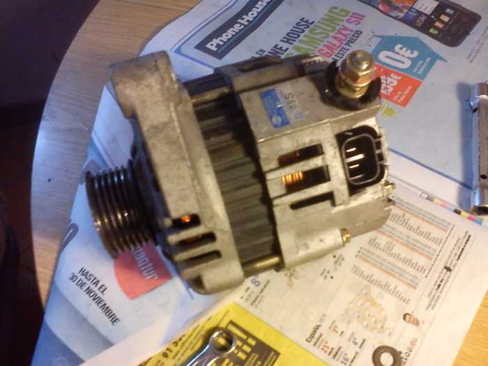
Muchas gracias, voy entendiendo, si sabía que a mí lo de las escobillas no me cuadraba ( choto, carbon te refieres a la escobilla verdad ? ), entonces, os paso un esquema de lo que he medido con el tester, yo creo que eso es así seguro, lo de la escobillas del negativo lo dejo, la del positivo no, porque es que viene directo de la tuerca donde se conecta el cable positivo, lo he puesto en el esquema, conectado al conector 1, (os pongo una foto tb:
Terminales 2, y 3 son los del conector doble, el 2 como veis va directo a un fusible de la cajita de al lado de la bateria, y directo a positivo de bateria. ESte esta marcado con LG en un libro de taller de un micra posterior, el del motor K12, el mio es el K11, y el otro, el 3 viene marcado como Lque vá al regulador, y veo del regulador al panel de pasa por el fusible de 10A debajo del volante, y luego va a la llave de contacto.
Lo que no entiendo como 2 terminales del conector a una escobilla, la negativa, (o menos positiva) ...........

Los diodos, no no están sueltos, si los 3 diodos los he medido desde el final de cada la fase hasta la misma tuerca del conector 1. Y los otros 3 desde un esparrago roscado, por la que luego pasa la tapa, osea negativo, hasta los los mismos extremos de bobinados. El bobinado estatórico tiene conexion en estrella, verifificado.
Entonces, yo creo que el alternador está bien, voy a montar otra vez el alternador, ojala sea una excesiva caida de tensión en los cables claro. Para medir tensión, cual será el cable que carga la bateria la, el gordo del conector 1 (yo creo que si), o el del 2 el LG, que va con uno de 10A ?, porque lo desconecto, arranco, a ver que tensión hay.
El alternador es un HItachi12V65A. A ver si encuentro por Inet el esquema.
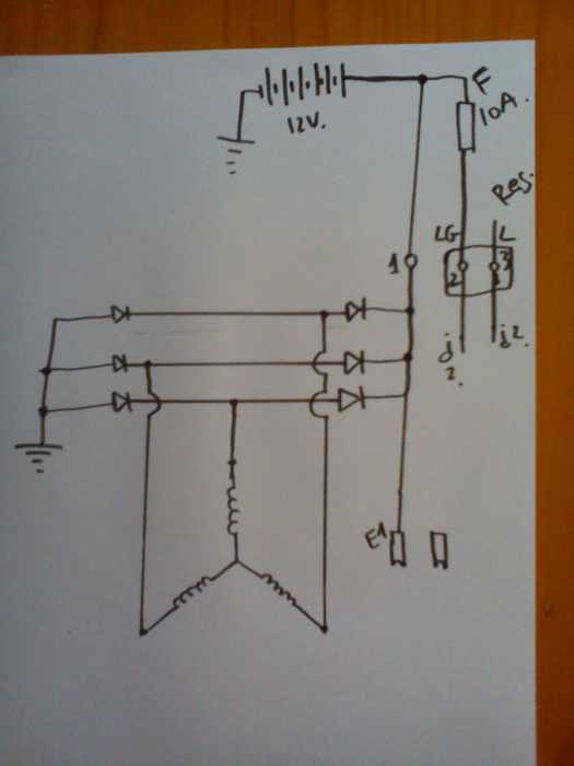
El nuevo esquema, la escobilla negativa no conectada, ya que no lo se, ni los conectores 2, y 3, el resto esta bien.
E1 sería una escobilla (directa del positivo de bateria), y la de al lado a la derecha la otra, no se si sabreis como va conectada a terminales 2 , y 3, continuidad no hay, vamos el tester no pita, hay algun componente electrónico intercalado.
Muchas gracias
Un saludo